In this post I’ll describe my favorite mesh data structure called half-edge data structure. It’s used primarily in Mesh/CAD applications and helps to make various advanced operations on the mesh such as subdivision or simplification.
Let’s start with the vertex and index buffer described in the previous post. The simplest way to display a model is through a list of triangles or what’s commonly referred to as a mesh (or triangle/polygon) soup, often rendered using Vertex Buffer and Index Buffer in OpenGL/Direct3D/Vulkan. Basically, if you want to render a quad, for example, you’ll need to fill you data in that way:
std::vector<glm::dvec3> vertices = {
    {0.0, 0.0, 0.0}, // Vertex 0
    {1.0, 0.0, 0.0}, // Vertex 1
    {1.0, 1.0, 0.0}, // Vertex 2
    {0.0, 1.0, 0.0}  // Vertex 3
};

std::vector<uint32_t> indices = {
    0, 1, 2, // Triangle 1
    2, 3, 0  // Triangle 2
};
Then pass both vectors to VB/IB in your favorite render system API. However, this triangle soup has one drawback: the inability to obtain information about the mesh topology. Why is this important?
When you’re working with a mesh represented as a “triangle soup,” each triangle is defined independently with its own set of vertex positions. This means that when you select and move a specific group of triangles, like a dark blue face made up of 8 triangles in the image below, there’s no inherent connection between these triangles and the rest of the mesh. As a result, when you move the selected triangles (cylinder on the left), the adjacent triangles remain in their original positions, leading to a gap or hole in the mesh (cylinder in the middle). This issue arises because the “triangle soup” representation lacks the topology information necessary to understand and maintain the connections between adjacent triangles. On the contrary, using a half-edge data structure fixes this issue (cylinder on the right). The half-edge data structure not only stores the geometric information (vertex positions) but also detailed topological information about how vertices, edges, and faces (triangles) are connected.
For simplicity, I am not mentioning normals and face colors in this post.

Half-edge data structure
And that’s why the half-edge data structure comes to our aid. First of all, we are adding notion of Half-edge, Edge, Face. The basic idea behind the half-edge data structure is that the:
[0] Edge consists of two so-called “Half-edges”. Let’s look at the image for the better clarity:
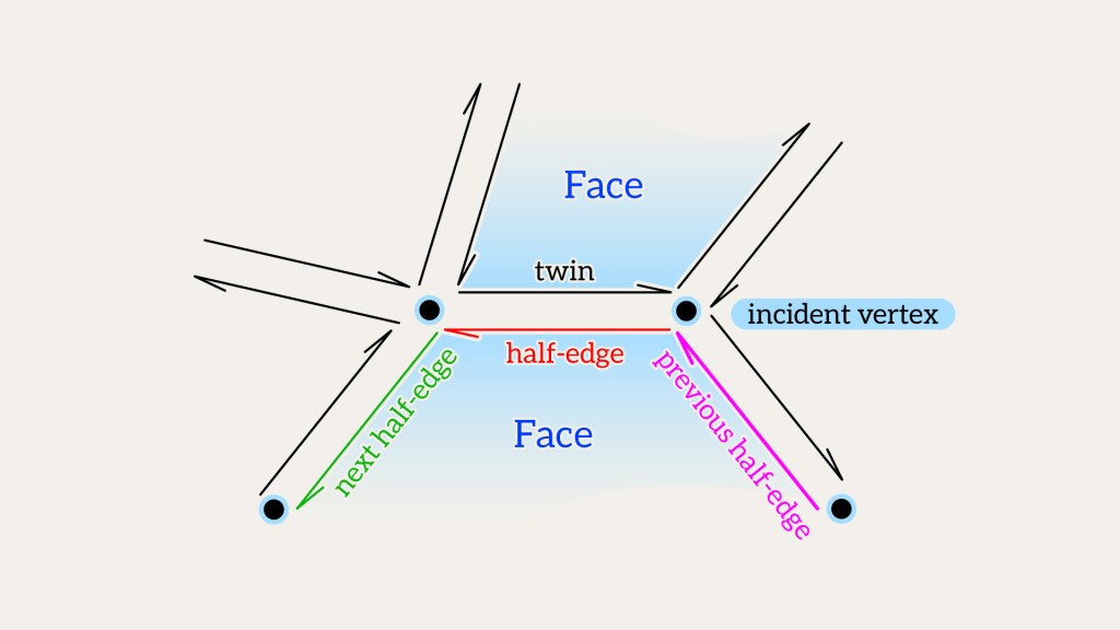
[1] Both half-edges are directed in opposite directions. Each half-edge contains pointers to:
- The face to which it belongs;
- The vertex to which the half-edge points;
- The next half-edge within its face, following a counter-clockwise (CCW) order;
- The previous half-edge;
[2] A vertex points to an outgoing half-edge.
[3] A face points to one of its bounding half-edges.
For simplicity, we will examine the implementation of the half-edge data structure as utilized in the OpenMesh library.
It’s worth noting that the term ‘pointer’ here doesn’t refer to a traditional pointer; rather, it is an index within an array.
Let’s return to our example with the quad and see what the half-edge data structure looks like for it.
First, let’s transfer the data from the initial code into the OpenMesh data structure. The add_face function constructs the half-edge data structure on the fly. This will be discussed in follow-up posts.
OpenMesh::TriMesh_ArrayKernelT<OpenMesh::DefaultTraitsDouble> mesh;
auto vh0 = mesh.add_vertex({0,0,0});
auto vh1 = mesh.add_vertex({1,0,0});
auto vh2 = mesh.add_vertex({1,1,0});
auto vh3 = mesh.add_vertex({0,1,0});
mesh.add_face(vh0, vh1, vh2);
mesh.add_face(vh2, vh3, vh0);
Graphically, the half-edge data structure for quad can be visualized as follows:

Faces:
| Face | Half edge |
| 0 | 4 |
| 1 | 5 |
| Edge | Half edge | Twin |
| 0 | 0 | 1 |
| 1 | 2 | 3 |
| 2 | 4 | 5 |
| 3 | 6 | 7 |
| 4 | 8 | 9 |
Vertices:
| Vertex | Half edge |
| 0 | 9 |
| 1 | 1 |
| 2 | 3 |
| 3 | 7 |
| Heh | Face | FromVH | ToVH | Next | Prev |
| 0 | 0 | 0 | 1 | 2 | 4 |
| 1 | -1 | 1 | 0 | 9 | 3 |
| 2 | 0 | 1 | 2 | 4 | 0 |
| 3 | -1 | 2 | 1 | 1 | 7 |
| 4 | 0 | 2 | 0 | 0 | 2 |
| 5 | 1 | 0 | 2 | 6 | 8 |
| 6 | 1 | 2 | 3 | 8 | 5 |
| 7 | -1 | 3 | 2 | 3 | 9 |
| 8 | 1 | 3 | 0 | 5 | 6 |
| 9 | -1 | 0 | 3 | 7 | 1 |
Positions:
| Vertex | Position |
| 0 | (0, 0, 0) |
| 1 | (1, 0, 0) |
| 2 | (1, 1, 0) |
| 3 | (0, 1, 0) |
OpenMesh stores all entities in the separate vectors inside OpenMesh::TriMesh_ArrayKernelT:
struct Edge {
	Halfedge  halfedges_[2];
};

struct Halfedge {
	FaceHandle      face_handle_;
	VertexHandle    vertex_handle_;
	HalfedgeHandle  next_halfedge_handle_;
	HalfedgeHandle  prev_halfedge_handle_;
};

struct Vertex {
	HalfedgeHandle  halfedge_handle_;
};

struct Face {
	HalfedgeHandle  halfedge_handle_;
};
class TriMesh_ArrayKernelT {
	std::vector<Vertex> vertices;
	std::vector<Edge> edges;
	std::vector<Face> faces;
	std::vector<Halfedge> halfedges;
//...
};
OpenMesh offers a set of functions for retrieving topological information about entities (Vertex, Half edge, Edge, Face). I will present a few examples to demonstrate why the half-edge data structure is advantageous for mesh manipulations and then delve into the implementation details in the next post.
How to Traverse the Edges of a Face in a Mesh
Let’s say you want to go through all the edges of a given face, fh, in a mesh and print edge vertices.
To do this, you can use the halfedge_handle function, which takes fh, and returns the half-edge that bounds the face fh.
The function next_halfedge_handle gives you the next half-edge in counter-clockwise (CCW) order.
The functions from_vertex_handle and to_vertex_handle return the start and end vertices of the half edge, respectively.
VertexHandle, HalfedgeHandle, EdgeHandle, and FaceHandle are simple wrappers around int32_t that act like “pointers” to the entities you need.
If your mesh is triangular (OpenMesh is designed to support polygonal faces, but we’ll stick with triangular for easier understanding), then it’s as simple as this:
OpenMesh::HalfedgeHandle heh = mesh.halfedge_handle(fh);
std::println("v0{} v1{}", mesh.from_vertex_handle(heh).idx(), mesh.to_vertex_handle(heh).idx());

heh = mesh.next_halfedge_handle(heh);
std::println("v0{} v1{}", mesh.from_vertex_handle(heh).idx(), mesh.to_vertex_handle(heh).idx());

heh = mesh.next_halfedge_handle(heh);
std::println("v0{} v1{}", mesh.from_vertex_handle(heh).idx(), mesh.to_vertex_handle(heh).idx());
Of course, you may want to use a loop to traverse:
OpenMesh::HalfedgeHandle heh = mesh.halfedge_handle(fh);
OpenMesh::HalfedgeHandle start_heh = heh;

do {
    OpenMesh::VertexHandle from_vh = mesh.from_vertex_handle(heh);
    OpenMesh::VertexHandle to_vh = mesh.to_vertex_handle(heh);
    std::println("v0{} v1{}", from_vh.idx(), to_vh.idx());
    heh = mesh.next_halfedge_handle(heh);
} while (heh != start_heh);
You can also achieve the same using iterators:
for (auto fh_it = mesh.cfh_begin(fh); fh_it != mesh.cfh_end(fh); ++fh_it) {
    OpenMesh::HalfedgeHandle heh = *fh_it;
    OpenMesh::VertexHandle from_vh = mesh.from_vertex_handle(heh);
    OpenMesh::VertexHandle to_vh = mesh.to_vertex_handle(heh);
    std::println("v0{} v1{}", from_vh.idx(), to_vh.idx());
}
Or using the ranges approach:
for (auto vh : mesh.fv_range(fh)) {
    OpenMesh::VertexHandle from_vh = mesh.from_vertex_handle(vh);
    OpenMesh::VertexHandle to_vh = mesh.to_vertex_handle(vh);
    std::println("v0{} v1{}", from_vh.idx(), to_vh.idx());
}
Or using new feature in OpenMesh 8.1 called SmartHandle (a handle that wraps a pointer to the mesh and an index, and provides convenient methods for retrieving various entities):
OpenMesh::SmartFaceHandle sfh = OpenMesh::make_smart(fh, mesh);
for (auto heh : sfh.halfedges())
    std::println("v0{} v1{}", heh.from().idx(), heh.to().idx());
A little off-topic. It’s interesting that previously in OpenMesh 8.0, for example, add_face returned a FaceHandle. Now, the same function returns a SmartFaceHandle. However, the old code still compiles without any issues, and the reason is that SmartFaceHandle inherits from FaceHandle, and if in the old code: FaceHandle fh = mesh.add_face(vh0, vh1, vh2); then now there is a slicing, as the return type SmartFaceHandle is sliced down to FaceHandle. Therefore, this is another reason to always use auto and not worry too much about how the type might change between library versions.
Traversing adjacent vertices to vertex
Let’s say you want to go through all the vertices next to a given vertex vh in a clockwise order. To do this, you need to start with the half-edge going out from the vertex, then find the twin of this half-edge, and keep going like this until you get back to the first half-edge you started with.

Here’s how you can write this in code:
OpenMesh::HalfedgeHandle start_heh = mesh.halfedge_handle(v0);
OpenMesh::HalfedgeHandle next_heh = start_heh;

do {
	std::println("v {}", mesh.to_vertex_handle(next_heh).idx());
	next_heh = mesh.opposite_halfedge_handle(next_heh);
	next_heh = mesh.next_halfedge_handle(next_heh);
} while (next_heh != start_heh);
Or using iterators:
for (auto vv_it = mesh.vv_iter(v0); vv_it.is_valid(); ++vv_it)
	std::println("v {}", vv_it->idx());
Or using ranges:
for (auto vh : mesh.vv_range(v0))
	std::println("v {}", vh.idx());
Or using SmartHandles:
OpenMesh::SmartVertexHandle svh = OpenMesh::make_smart(v0, mesh);
for (auto vh : svh.vertices())
	std::println("v {}", vh.idx());
The key concept is that by employing the loops provided above, you can traverse any desired features of a mesh. You can gather all faces adjacent to a vertex or collect all outgoing edges from a vertex simply by utilizing technique with the next_halfedge_handle and opposite_halfedge_handle functions. Alternatively, you can take advantage of convenient wrappers provided by OpenMesh, such as SmartHandle(s), or use iterator/range algorithms to achieve the same goals.
To summarize, the OpenMesh library offers a range of traversal functions that allow you to navigate through a mesh and interact with its neighbor elements. Here’s an overview, where action represents a user-defined operation you can perform on each neighbor element:
Vertex (sourceVh) to Vertices/Edges/Faces
for (auto vh : sourceVh.vertices())
	action(vh);

for (auto eh : sourceVh.edges())
	action(eh);

for (auto fh : sourceVh.faces())
	action(fh);
Edge (sourceEh) to Vertices/Edges/Faces
action(sourceEh.v0());
action(sourceEh.v1());
It rather interesting question – what should we consider as the neighboring edges of a given edge? For the purposes of selection, it’s convenient to simply return all edges adjacent to the vertices at the start (sourceEh.v0()) and end (sourceEh.v1()) of the given edge.
for (auto vh : { sourceEh.v0(), sourceEh.v1() })
	for (auto eh : meshData.ve_range(vh))
		if (eh != sourceEh)
			action(eh);

action(sourceEh.h0().face());
action(sourceEh.h1().face());
Faces (sourceFh) to Vertices/Edges/Faces
for (auto vh : sourceFh.vertices())
	action(vh);

for (auto eh : sourceFh.edges())
	action(eh);

for (auto fh : sourceFh.faces())
	action(fh);
Summary
In this post, the basics of the half-edge data structure were explored and demonstrated methods to populate it with geometrical data and navigate through its features (Vertex, Edge, Face) using the OpenMesh library. Next time, I’ll dive deeper and look at how to add and remove faces from our mesh using Half-edge data structure.

Leave a comment