Today, I’d like to dedicate a post to the topic of mesh stitching.
Stitching meshes is usually necessary when they contain gaps, cracks, or thin, narrow holes that can be stitched together instead of being filled. Such cracks might appear due to incorrect data conversion or as a result of geometric algorithms – for example, merging two meshes.
This task interests me because it demonstrates how a solution from real life (stitching fabric with a needle) can be applied in programming. Generally, I aim to write posts about the philosophy of programming, but they somehow always end up being very technical. 🙂
Although there’s nothing revolutionary about this method, it’s extremely useful for developing one’s skills as a geometric programmer.
Problem Definition
Imagine a half-edge mesh with cracks or narrow, elongated holes.
The goal is to stitch the sides of these cracks if their width (or radius) is smaller than a specified threshold (indicated by the purple circles in the picture).

To start, we’ll introduce a function that collapses one vertex into another, as this will be essential for stitching.
void collapse(SmartVertexHandle from, SmartVertexHandle to);
This function adjusts the topology by:
- Removing the vertex
from; - Reconnecting the faces incident to
fromso that they are now associated withto; - As a result,
tobecomes shared among its original faces and the faces offrom; - The vertex
fromis deleted;

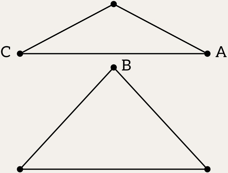
The image shows an example of a collapse from one vertex (from == A) to another (to == B).
For some reason, OpenMesh does not provide such a function. It only includes the collapse(EdgeHandle eh) function. However, having this type of functionality would be very useful in many applications.
Our new collapse function should behave like collapse(EdgeHandle eh) in cases where an edge exists between from and to. This is the simplest scenario.
But what if there is no edge between them? In this case, we need to replace from with to in the faces incident to the from vertex. The obvious, albeit inefficient, solution (provided here just to demonstrate the logic) is as follows:
std::vector<std::pair<OpenMesh::FaceHandle, std::vector<OpenMesh::VertexHandle>>> newFaces;

for (auto fh : from.faces()) {
	std::vector<OpenMesh::VertexHandle> updatedVertices;	// Although highly inefficient, it is useful for demonstration purposes

	for (auto vh : fh.vertices()) {
		if (vh == from)
			updatedVertices.push_back(to);
		else
			updatedVertices.push_back(vh);
	}

	newFaces.emplace_back(fh, std::move(updatedVertices));
}

for (auto fh : from.faces())
	meshData.delete_face(fh, false);  // The parameter false is necessary to ensure that when a face is removed, its vertices are not deleted
Now, iterate through newFaces and create new faces incident to the to vertex.
for (const auto& [_, vertices] : newFaces)
    meshData.add_face(vertices[0], vertices[1], vertices[2]);
This approach works, but it does not reuse the old face handles. As a result, instead of reusing the faces that were incident to the from vertex, you end up with new faces attached to the to vertex. Additionally, new edges (and their corresponding half-edges) are introduced. A smarter solution is to reindex the existing half-edge data structure directly, without invoking the delete_face and add_face functions.
Stitching a Crack. Basic Approach
A crack is typically represented as a sequence of vertices, which can be easily extracted by identifying all border edges and their corresponding vertices.
The key question is: which pair of vertices in the sequence should be collapsed? Let’s begin with a simple case where the sequence appears as follows:

In this scenario, we can:
- Sequentially pick the two closest, unconnected vertices (A, B on the picture) in the sequence.
- Compute the average position of these two vertices.
- Collapse them using
collapse.
By repeating this process, we can stitch the crack.
Challenges with the Basic Approach
Case 1: Large Gaps
If the gap between two vertices (A and B in the picture) is too large, the algorithm might skip stitching them because the distance exceeds the permissible threshold:
- The problem remains unresolved.
- These “holes” create invalid topology, which can disrupt further use of the model.
Case 2: Skewed Merging

If the algorithm forcibly merges the closest vertices (B->A), it might:
- Collapse two vertices, while another nearby vertex (C) is left outside the threshold.
- This creates distortions in the model, breaking its proportions and dimensions.
These problems are particularly common in T-junctions.
Better Solution: Edge Splitting
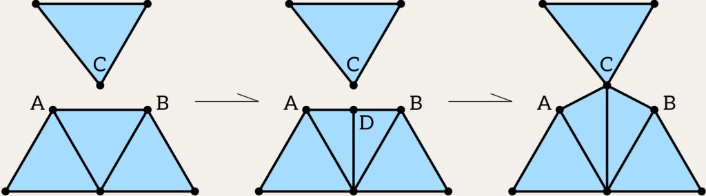
To avoid these problems, instead of looking for the nearest vertex, we can:
- Find the nearest edge (AB on the picture) to the given vertex (C).
- Project the vertex onto this edge, obtaining the closest point on the edge (D).
- Perform an edge-split operation at the projection point, creating a new vertex (D).
- Merge the original vertex with the newly created vertex (D->C).
Final Algorithm
1. Start with a sequence of vertices defining the crack.
2. Iteratively find the closest features (either vertex-vertex or vertex-edge) in the sequence. This can be done by examining each vertex in the sequence and checking the nearest feature to the current vertex. A feature refers to either a vertex or an edge. The result of each iteration will be the feature and the distance to it, and if the feature is an edge, also the barycentric coordinates (ratio). Thus, in each iteration, the closest feature with the smallest distance needs to be selected. It is very important to filter out nearby features that lie in a straight line with the current vertex (as shown in the image below); otherwise, T-junctions will be created.
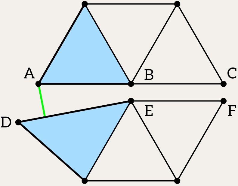
For example, for vertex A, B is not an option because it’s connected with vertex A. And vertex C is not an option because it lies on a straight line with A and B. This means that if you collapse vertex C into A, you immediately get a T-junction. Good candidates are: (A,D, 0.25), (A,E) and (E,F). Note, that first pair contains ratio equals 0.25 – if we project A to DE segment, we’ll see that projection (point G) of A will lie on a first quarter of DE segment. Therefore, point G is the closest to vertex A and (A,D, 0.25) is the most suitable candidate. And if we merge A->G, we’ll have this one:

3. Apply the appropriate operation:
- Vertex-vertex case: Collapse two vertices, if the best candidate is the vertex.
- Vertex-edge case: If the best candidate is an edge, split the edge at the projection point and collapse the original vertex with the newly created one. It is important to note that in this case, adding a small epsilon to the ratio is advisable, as numerical errors may occur when calculating the ratio. The epsilon value can range from 0 to 1. In a sense, this resembles vertex snapping. If you make the epsilon large, there won’t be an edge split, but rather a collapse of one vertex into another. This can help avoid frequent splitting. You can experiment with this parameter, but usually, epsilon == 0.2 is a good choice.
4. After each operation, the sequence might split into smaller subsequences.

On the picture for sequence A,B,C,D,E,F, after collapsing E->B, there are two subsequences A,B,F and B,C,D.
5. Process each subsequence recursively until no more stitching is needed.
Summary
This algorithm mimics real-life stitching with a needle: finding the closest points, connecting them, and repeating the process until the crack is closed. By combining edge splitting and vertex merging, we handle complex cases like T-junctions, ensuring a robust and accurate result.
Links
Stitching and Filling: Creating Conformal Faceted Geometry by Paresh S. Patel, D. Marcum, M. Remotigue

Leave a comment